Guidelines for customers that opt for the Eurocircuits standard panel based on a Single PCB layout
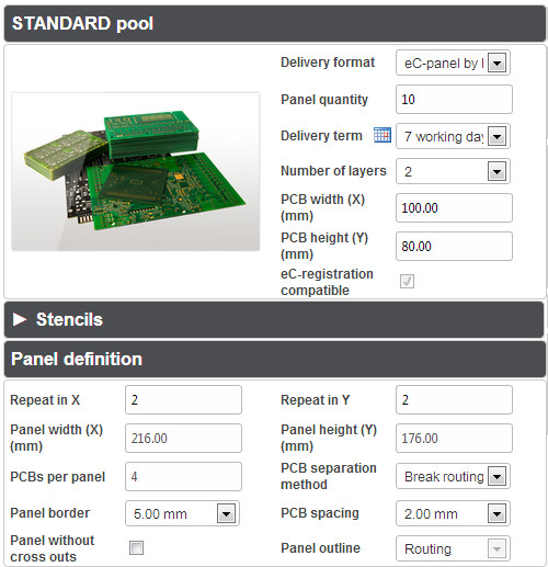
For this option you select ‘eC panel by Eurocircuits
Guidelines
- The easiest way to get a panel for one type of circuit only. (Panels with multiple designs are possible trough selection ‘ Eurocircuits according to customer specific rules).
- Minimum dimensions of the single design to be panelised is 5.00 x 5.00 mm for STANDARD pool
- The maximum panel size is 250.00 x 350.00 mm- This is also the maximum size of a panel to be processed on our eC prototype equipment.
- Individual boards in the panel can be separated by Break-rout or V-cut (scoring) -The selection ‘None’ means no separation at all, so the whole panel is delivered as one pcb, with only the outer contour of the panel milled.
- Important for V-cut
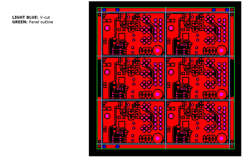
- For V-cut ( or scoring) the minimum panel size is 100 x 100 mm
- V-cut is always over the full length of the panel ( no jump-scoring)
- Min. V-cut clearance : 0.45 mm
- Panel borders
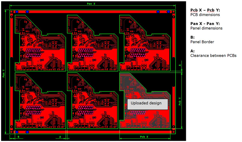
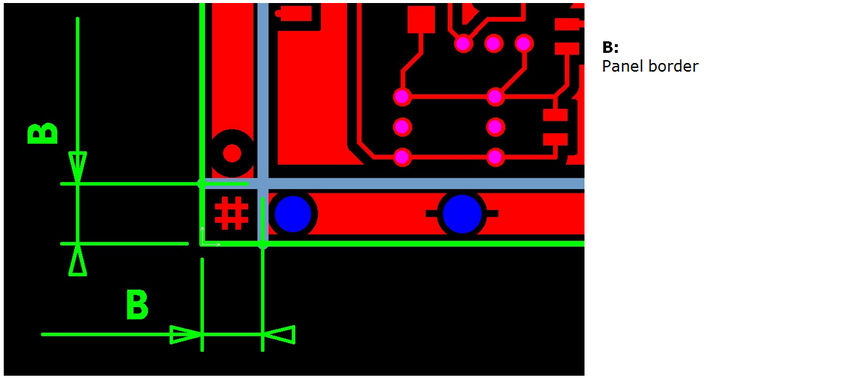
- To make a stable panel we propose a minimum border of 2 x 5 mm in X and Y
- Available options for panel borders:
- 5.00 mm – 7.00 mm – 10.00 mm – 20.00 mm
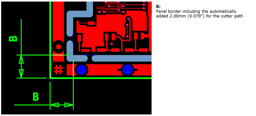
- The calculate and order tool will automatically add 2.00 mm on all sides for the cutter path if the panel is to be break-routed.
- Available options for panel borders:
- Standard fiducials, Imperial tooling holes ( 0.125″) and eC-registration tooling holes ( 3.00 mm) are included in the panel border.
- For special fiducials, please supply pre-panelised data (select ‘ Customer, according to customer specific panel rules’)
-
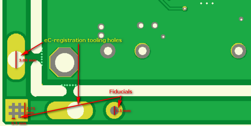
- To make a stable panel we propose a minimum border of 2 x 5 mm in X and Y
- Clearance between PCB’s
- The minimum ( and standard) clearance between PCB’s for break-routing is 2.00 mm. Any larger value is OK.
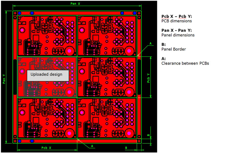
- In case of V-cut there is no clearance between the PCB’s – however take care of the V-cut clearence
- The minimum distance beween any two V-cut lines is 5.00 mm.
- Available clearances: 0.00 mm ( V-cut only) – 2.00 mm ( Break-rout only) – 5.00 mm – 10.00 mm – 15.00 mm – 20.00 mm
- In case of V-cut (scoring) note that all lay-out elements and holes must be at least 0.45 mm away from the edge of the board. (picture left)
-
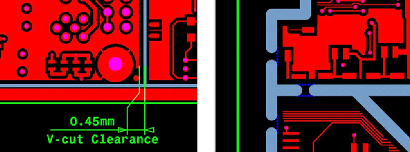
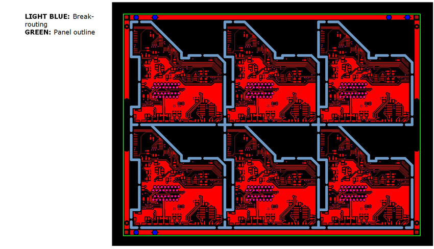
- The V-cut-line and break-rout path are pictured light blue, the break-tabs dark blue
- Break-rout tabs ( picture right) will be defined by our engineers to ensure a stable panel.
- Break-rout tabs will be drilled to break inside the board profile for a cllean break-out.
Practical examples
- Panel example with Break-routing
- Panel example with V-cut (scoring)
- Corner details
- For panel with Break-routing
- For panel with V-cut

